
Industrial pneumatic systems depend on controlled movement through pipes, tubes, valves and fittings. In many applications, the direction of that movement is just as important as pressure or flow rate. When compressed air or another compatible medium moves in an unintended direction, it can interfere with the intended operation of the circuit.
Pneumatic check valves are designed to address this issue by allowing flow in one direction while restricting it in the opposite direction. For this reason, they are also commonly referred to as non-return valves. They can form an important part of pneumatic control circuits where maintaining a defined direction of flow is necessary. Understanding how check valves operate can make it easier to select suitable pneumatic valve fittings for an industrial system.
What Is Reverse Flow in a Pneumatic System?
A pneumatic circuit is generally designed so that air or another medium follows a planned path through the system. Pressure differences help create this movement and allow different components to perform their intended functions.
However, changing pressure conditions can create the possibility of movement in the opposite direction. Without an appropriate method of controlling that movement, the medium may travel back through part of the circuit.
Reverse flow is therefore not simply about how much air is moving. It concerns whether the movement follows the direction intended by the system design.
Check valves provide a relatively straightforward way of establishing that directional control.
How Does a Pneumatic Check Valve Work?
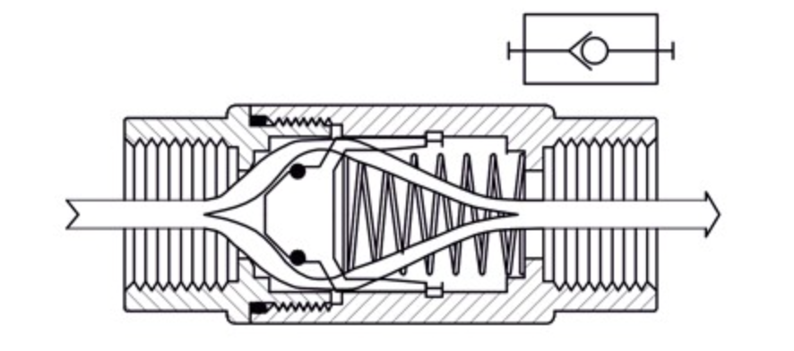
The basic operating principle of a pneumatic check valve is simple. Flow is permitted in one direction and restricted in the other.
When sufficient pressure is applied from the permitted direction, the internal valve mechanism opens and allows the medium to pass. If the pressure conditions change or movement begins in the opposite direction, the valve closes the passage.
The pneumatic check valves are specifically designed for single-direction flow. The documented CV01 series shuts the fluid passage when the pressure difference falls below 0.258 bar.
This automatic response means directional control can occur according to pressure conditions without requiring continuous manual operation.
Why Are They Called Non-Return Valves?
The alternative term “non-return valve” describes the component’s purpose particularly well.
Once the medium has travelled through the valve in the permitted direction, the design prevents it from simply returning through the same path in the opposite direction.
This principle can be compared conceptually with the directional function of a diode in an electrical circuit.
Although pneumatic and electrical systems operate differently, the comparison provides a simple way of understanding the role of directional control.
See also: Expert Guide to Selling Your Trade Business
Pressure Difference Is Central to Valve Operation
Check valve operation depends on pressure conditions.
A valve does not simply remain permanently open in one direction. There needs to be sufficient pressure difference to operate the internal mechanism and permit flow through the component.
This is why pressure-related specifications should be examined when selecting a check valve. The documented stainless steel pneumatic check valve range, for example, has a stated pressure rating of 0.5 to 40 bar.
A valve should therefore be selected according to the operating conditions of the actual system rather than merely according to its physical connection size.
Why Preventing Reverse Flow Matters
Directional control helps maintain the intended behaviour of a pneumatic circuit.
If a circuit has been designed for movement through a particular pathway, uncontrolled reverse movement can interfere with how other components are expected to operate. A check valve establishes a defined direction and closes when the necessary pressure conditions are no longer present.
This can be particularly useful in sophisticated or sensitive pneumatic control circuits where directional flow is an important part of the system design.
The purpose is not to control every aspect of the pneumatic system with one component. Instead, the check valve performs the specific function of helping maintain one-way movement.
Valve Size Needs to Match the System
Selecting pneumatic valve fittings involves more than understanding what the component does. Physical sizing also matters.
The documented pneumatic check valve range is available in pipe-thread sizes from 1/8 inch through 1 inch.
Different sizes allow valves to be incorporated into different system configurations, but buyers should not assume that choosing a larger valve automatically provides better performance.
The correct size needs to correspond with the broader circuit design, connections and operating requirements. Technical specifications and system requirements should therefore guide the selection.
End Connections Need Careful Attention
A check valve must also connect correctly with the surrounding pneumatic components.
Different thread standards may be used depending on the equipment and system. The range includes BSP, BSPT, NPT and SAE straight-thread end connections.
Connection configurations can also vary. The documented series includes female-to-female, male-to-female and female-to-male options in BSP parallel configurations, as well as female-to-female NPT models.
These differences demonstrate why selecting a valve solely according to nominal pipe size can be insufficient. Thread type and connection configuration also need to be compatible.
Inline and Port-Mounted Designs Offer Different Options
The physical arrangement of the pneumatic circuit can influence the type of valve required.
Compact inline check valves can be incorporated within a line, while port-mounted configurations provide another installation option. Both compact inline and port-mounting models are identified within the product information.
The appropriate configuration depends on the system layout, available installation space and connection requirements.
This highlights another reason pneumatic components should be selected according to the complete circuit rather than individually. Two valves can perform the same basic non-return function while being designed for different installation arrangements.
Temperature Ratings Should Not Be Overlooked
Temperature is another important operating parameter.
Industrial environments can expose pneumatic components to different temperature conditions, so the valve needs to be suitable for the environment and medium involved.
The documented stainless steel check valves have a stated temperature rating of up to 180°C.
However, this figure should not be interpreted as meaning every pneumatic application should operate near that limit. Instead, it establishes a technical parameter that should be compared with the requirements of the particular system.
Pressure, temperature and compatibility should be evaluated together when choosing components.
Why Stainless Steel Is Used for Pneumatic Check Valves
Material selection is another part of pneumatic valve design.
The check valves are manufactured from stainless steel. Stainless steel is widely used for industrial valves and fittings where durable construction and suitability for demanding operating environments are important considerations.
However, material should still be evaluated according to the actual medium and operating conditions.
Choosing stainless steel does not remove the need to review other specifications. Pressure, temperature, thread type, valve size and system compatibility remain important regardless of the construction material.
Installation Direction Matters
Because a check valve is specifically designed for unidirectional flow, its orientation within the circuit matters.
Installing a directional component incorrectly can prevent the circuit from operating as intended. The required flow direction should therefore be identified before installation, and the manufacturer’s instructions should be followed.
This may seem straightforward, but directional components should never be installed purely according to how conveniently they fit within the available space.
System diagrams, flow markings and technical documentation can help confirm the intended orientation before the pneumatic circuit is placed into operation.
Check Valves Are One Part of a Larger Pneumatic Circuit
A pneumatic system can contain many components performing different functions.
Fittings connect sections of the circuit, while check valves provide directional control. Other components may regulate flow, control pressure or perform additional functions required by the system.
For this reason, pneumatic valve fittings should not be selected in isolation. A suitable check valve needs to work with the connections, pressure conditions, temperature requirements and overall design of the surrounding circuit.
A component can have appropriate individual specifications but still be unsuitable if those specifications do not match the system where it will be installed.
Technical Specifications Should Guide Selection
Check valves may appear relatively simple, but several specifications need to be considered together.
The available pipe-thread size should match the connection requirements. The thread standard needs to correspond with surrounding components. Pressure and temperature ratings need to accommodate operating conditions, while the physical configuration should suit the system layout.
Flow direction and valve operating characteristics must also be understood.
Reviewing these details before installation can help ensure that the chosen valve performs the non-return function expected within the particular pneumatic circuit.
Conclusion
Pneumatic check valves help prevent reverse flow by permitting movement in one direction and closing the passage when operating conditions no longer support that intended flow. This makes them useful as non-return components within industrial pneumatic control circuits.
However, effective directional control depends on choosing the correct valve for the system. Pipe-thread size, pressure rating, temperature rating, end connection, installation configuration and operating characteristics all need to be considered.
When selecting pneumatic valve fittings, understanding these technical requirements is just as important as understanding the basic purpose of the component. A correctly specified check valve can then perform its intended role as part of a properly designed pneumatic system.


 By
By